T: +86-577-59970799
E: wpt0125978@163.com
E: wpt0125978@163.com
No.17 Binhai 3rd Road, Yongxing Street, Longwan District, Wenzhou City, Zhejiang Province


| Quantity: | |
|---|---|


WTM
WEIDU
The WT series gas turbine flow meter is a high-precision and highly reliable precision metering instrument. It is suitable for measuring various single-phase gases and is widely applied in industries such as city gas, petroleum, chemical, power, and metallurgy for gas measurement.
The WT series gas turbine flow meter delivers excellent low-pressure and high-pressure metering performance, making it ideal for accurate measurement of large-flow gas volumes. Depending on user requirements, our company can provide turbine flow meters with different accuracy classes and performance specifications.
High accuracy, excellent repeatability, and wide turndown ratio (up to 1:20).
Integrated flow conditioner reduces straight pipe requirements (≥2DN upstream, ≥1DN downstream).
The flow meter's volume corrector can rotate freely by approximately 360°, ensuring easy reading in any installation orientation.
Low rotational speed, long service life, low pressure loss, and high precision.
Equipped with high-accuracy digital temperature and pressure sensors; the digital pressure sensor features built-in temperature compensation and calibration, ensuring high pressure measurement accuracy, long-term stability, and minimal temperature drift.
Automatically detects medium temperature and pressure, performing temperature, pressure, and compressibility factor corrections to convert operating condition volume flow/total volume to standard condition volume flow/total volume.
Utilizes advanced ultra-low power consumption technology, enabling long-term operation powered by internal batteries.
Features large-capacity data storage with tamper-proof function, automatically recording critical data modifications and historical data.
Real-time data storage prevents data loss during battery replacement or power failure; internal parameters are permanently retained without power.
Supports embedded 4G or NB wireless modules, enabling various wireless meter reading systems. Can transmit wirelessly a limited number of times per day (once daily) via internal battery without external power, or support unlimited data transmission with external power supply.
When fluid passes through the flow meter, it is rectified and accelerated under the action of the flow conditioner (or straightener). Due to the certain angle between the blade structure of the impeller and the flow direction, a rotational torque is generated on the impeller. After overcoming the frictional torque and fluid resistance torque, the turbine begins to rotate. Within a certain flow range, the rotational angular velocity of the turbine is approximately proportional to the volumetric flow rate of the fluid.
The mechanical structure drives the mechanical counter to operate.
Based on the principle of electromagnetic induction, a magnetically sensitive sensor detects pulse signals from a synchronously rotating transmitter disc. These signals are proportional to the volumetric flow rate of the fluid and are transmitted to the volume corrector. Together with temperature, pressure, and other signals, they undergo computational processing and are displayed on the screen. The structure is shown in FIG.1.
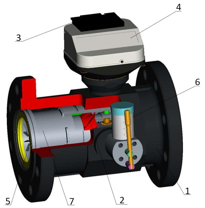
1. Flow Meter Housing 2. Turbine Rotor 3. LF Pulse Generator and Tamper-Evident Device 4. Index Head and 8-Digit Counter 5. Flow Rectifier 6. Lubrication Oil Pump 7. Measuring Cartridge
FIG.1 Structure Diagram of Gas Turbine Flow Meter
Accuracy class: within the specified flow range and operating conditions, the flow meter has an accuracy class of 1.0 or 1.5.
Class 1.0: 0.2Qmax ~ Qmax: ±1.0%; Qmin ~ 0.2Qmax: ±2.0%.
Class 1.5: 0.2Qmax ~ Qmax: ±1.5%; Qmin ~ 0.2Qmax: ±3.0%.
Temperature Display Error: ≤±0.5 °C
Pressure Display Error: ≤±0.2%
Mechanical Performance Indicators
Flow Meter Model Specifications and Basic Parameters are shown in Table 1.
Table 1
Nominal Diameter (DN) | G-Rating | Flow Range (m3/h) | Impeller Material | Pressure (MPa) | Remark |
50 (2") | G40 | 6 ~ 65 | Aluminum Alloy | 1.6 2.5 4.0 6.3 | Housing Material: ≤ 1.6 MPa: Cast Aluminum Alloy; > 1.6 MPa: Carbon Steel or Stainless Steel |
G65 | 8 ~ 100 | ||||
G100 | 10 ~ 160 | ||||
80 (3") | G100 | 8 ~ 160 | |||
G160 | 13 ~ 250 | ||||
G250 | 20 ~ 400 | ||||
100 (4") | G160 | 13 ~ 250 | |||
G250 | 20 ~ 400 | ||||
G400 | 32 ~ 650 | ||||
150 (6") | G400 | 32 ~ 650 | |||
G650 | 50 ~ 1000 | ||||
G1000 | 80 ~ 1600 | ||||
200 (8") | G650 | 50 ~ 1000 | |||
G1000 | 80 ~ 1600 | ||||
G1600 | 130 ~ 2500 | ||||
250 (10") | G1000 | 80 ~ 1600 | Housing Material: Carbon Steel or Stainless Steel | ||
G1600 | 130 ~ 2500 | ||||
G2500 | 200 ~ 4000 | ||||
300 (12") | G1600 | 130 ~ 2500 | |||
G2500 | 200 ~ 4000 | ||||
G4000 | 320 ~ 6500 |
① The flow range listed in the table refers to the flow range during factory calibration of the product (with air as the medium under normal temperature and pressure).
② As pressure increases, the flow range also expands accordingly.
The flow meter dimensions are shown in FIG.2 and listed in Table 2. The flow meter adopts flange connections, with the flange dimensions in accordance with the GB/T9124-2019 standard.
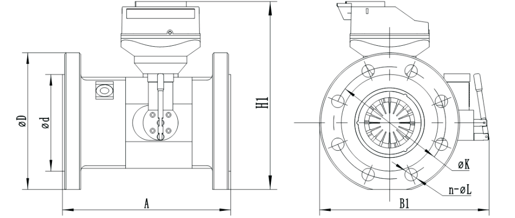
FIG.2 WTM Outline Dimensions Drawing
Unit: mm Table 2
Nominal Diameter | A Distance Between Two Flanges | Width | Height | D Flange Outside Diameter | K Bolt Center Distance | Bolt Hole Pattern | d Sealing Surface | ||||
B | B1 | H | H1 | H2 | n | L | |||||
50 | 150 | 215 | 225 | 317 | 230 | 380 | 165 | 125 | 4 | 18 | 102 |
80 | 240 | 232 | 242 | 350 | 260 | 410 | 200 | 160 | 8 | 18 | 138 |
100 | 300 | 252 | 262 | 370 | 280 | 430 | 220 | 180 | 8 | 18 | 158 |
150 | 450 | 312 | 322 | 428 | 338 | 488 | 285 | 240 | 8 | 22 | 212 |
200 | 600 | 381 | 397 | 496 | 407 | 557 | 340 | 295 | 12 | 22 | 268 |
250 | 375 | 445 | 455 | 559 | 469 | 619 | 405 | 355 | 12 | 26 | 320 |
300 | 450 | 490 | 490 | 605 | 515 | 665 | 460 | 410 | 12 | 26 | 378 |
When ordering this product, users should select the appropriate specification based on the nominal pipeline pressure, maximum medium pressure, medium temperature, flow range, and environmental conditions, and choose a suitable electronic head according to actual needs.
When placing an order, please fill out the form correctly according to the following format.