T: +86-577-59970799
E: wpt0125978@163.com
E: wpt0125978@163.com
No.17 Binhai 3rd Road, Yongxing Street, Longwan District, Wenzhou City, Zhejiang Province


| Quantity: | |
|---|---|


WRFD
WEIDU
The IC Card Gas Flow Meter is our company's dedicated intelligent device designed for gas flow measurement. It features temperature, pressure, and compressibility factor compensation, and displays key parameters such as medium temperature, pressure, total volume under operating/standard conditions, instantaneous flow rates, and remaining gas volume (or balance). The meter supports IC card recharge, optional data remote transmission and valve control, and offers multiple signal output interfaces.
With built-in IoT communication modules, valve control electronics, and IC card functionality, it enables various wireless communication networks. This allows for real-time software upgrades, dynamic pricing, online payments, and remote valve operations. An integrated smart solution, this flow meter is well-suited for measurement, trade settlement, and comprehensive management in urban gas, petroleum, and chemical industries.
Adopting advanced ultra-low power consumption technology, it operates efficiently on internal batteries for extended periods.
The device can be embedded with 4G or NB wireless modules, enabling various forms of wireless meter reading systems. Powered by built-in batteries, it supports limited daily wireless transmissions without external power, ensuring ease of use. Alternatively, with external power supply, unlimited wireless transmissions can be achieved.
Integrating gas metering, prepayment, and valve control into one system, it features self-diagnosis and alarm functions for high reliability. An LCD display provides clear, intuitive readings for user convenience.
It supports settlement by amount or gas volume, accommodating tiered gas pricing.
With real-time data storage, the device prevents data loss during battery replacement or power failure, ensuring long-term preservation of internal parameters in case of power outages.
Equipped with high-capacity data storage, it offers anti-tampering protection and automatically logs critical data modifications and historical records.
The device includes anti-theft functionality, capable of detecting, recording, and alerting in the event of unauthorized gas extraction.
Table 2 Mechanical Performance Specifications
Nominal Diameter DN(mm) | G-Rating | Flow Range (m3/h) | Start-up Flow (m3/h) | Max. Pressure Loss (kPa) |
20(0.8") | G6 | 0.2 ~ 10 | 0.04 | 0.15 |
25(1") | G10 | 0.4 ~ 16 | 0.06 | 0.20 |
G16 | 0.4 ~ 25 | 0.06 | 0.25 | |
40(1.5") | G16 | 0.5 ~ 25 | 0.07 | 0.10 |
G25 | 0.5 ~ 40 | 0.07 | 0.10 | |
G40 | 0.5 ~ 65 | 0.07 | 0.25 | |
50(2") | G16 | 0.5 ~ 25 | 0.07 | 0.10 |
G25 | 0.5 ~ 40 | 0.07 | 0.10 | |
G40 | 0.5 ~ 65 | 0.07 | 0.25 | |
G65 | 0.5 ~ 100 | 0.07 | 0.35 | |
80(3") | G100 | 0.8 ~ 160 | 0.10 | 0.35 |
G160 | 1.6 ~ 250 | 0.15 | 0.40 | |
100(4") | G160 | 1.6 ~ 250 | 0.15 | 0.35 |
G250 | 2.0 ~ 400 | 0.30 | 0.40 | |
G400 | 3.0 ~ 650 | 0.60 | 0.70 | |
150(6") | G400 | 6.5 ~ 650 | 0.70 | 0.60 |
G650 | 6.5 ~ 1000 | 0.70 | 0.80 | |
200(8") | G1000 | 10 ~ 1600 | 1.20 | 0.70 |
Within the specified flow range and operating conditions, the accuracy class of the flow meter is Class 1.0 or Class 1.5.
Class 1.0: 0.20Qmax ~ Qmax: ±1.0%; Qmin ~ 0.20Qmax: ±2.0%
Class 1.5: 0.20Qmax ~ Qmax: ±1.5%; Qmin ~ 0.20Qmax: ±3.0%
Temperature indication error: ≤±0.5 °C
Pressure indication error: ≤±0.2%
The horizontal dimensions of the IC card gas Roots flow meter are shown in FIG.1, with specific values provided in Table 2. The flow meter adopts a flange connection, and the flange dimensions comply with the GB/T 9124-2019 standard.
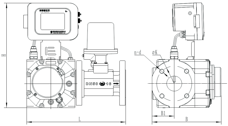
FIG.1
Unit: mm Table 2
Nominal Diameter DN/mm | G-Rating | L | H | B | B1 | K | n-d | Remark | ||
WRZ/ WRD | WRM | WRZ | WRM/ WRD | |||||||
20(0.8") | G6 | 273 | 337 | / | 198 | / | 55 | 75 | 4×M12 | M12×35 |
25(1") | G10 | 273 | 337 | 137 | 198 | 247 | 55 | 85 | 4×M12 | M12×35 |
G16 | 273 | 337 | 137 | 198 | 247 | 55 | 85 | 4×M12 | M12×35 | |
40(1.5") | G16 | 340 | 375 | 172 | 246 | 289 | 79 | 110 | 4×M16 | M16×50 |
G25 | 340 | 375 | 172 | 246 | 289 | 79 | 110 | 4×M16 | M16×50 | |
G40 | 340 | 375 | 172 | 246 | 289 | 79 | 110 | 4×M16 | M16×50 | |
50(2") | G16 | 353 | 375 | 172 | 246 | 289 | 79 | 125 | 4×M16 | M16×50 |
G25 | 353 | 375 | 172 | 246 | 289 | 79 | 125 | 4×M16 | M16×50 | |
G40 | 353 | 375 | 172 | 246 | 289 | 79 | 125 | 4×M16 | M16×50 | |
G65 | 353 | 375 | 172 | 246 | 289 | 79 | 125 | 4×M16 | M16×50 | |
80(3") | G100 | 378 | 375 | 172 | 298 | 343 | 100 | 160 | 8×M16 | M16×50 |
G160 | 447 | 465 | 261 | 346 | 390 | 122 | 160 | 8×M16 | M16×50 | |
100(4") | G160 | 473 | 465 | 261 | 346 | 390 | 122 | 180 | 8×M16 | M16×50 |
G250 | 473 | 465 | 261 | 446 | 490 | 181 | 180 | 8×M16 | M16×50 | |
G400 | 473 | 465 | 261 | 446 | 490 | 181 | 180 | 8×M16 | M16×50 | |
150(6") | G400 | 724 | 497 | 646 | 690 | 301 | 240 | 8×M20 | M20×60 | |
G650 | 724 | 497 | 646 | 690 | 301 | 240 | 8×M20 | M20×60 | ||
200(8") | G1000 | 800 | 549 | 855 | 899 | 400 | 295 | 12×M20 | M20×60 | |
For the vertical installation of the IC-card gas Roots flow meter, the external dimensions are shown in FIG.2 and listed in Table 3. The flow meter adopts a flanged connection, with flange dimensions in accordance with GB/T 9124-2019.
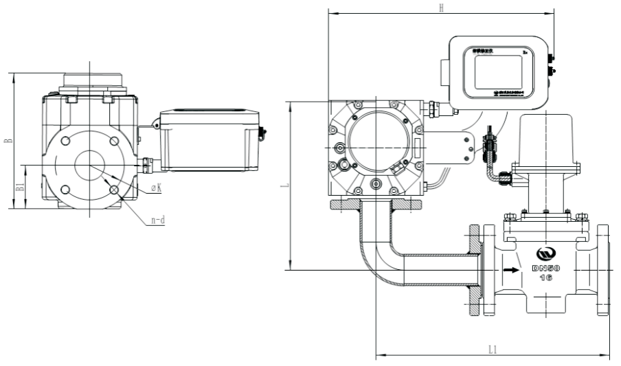
FIG.2
Unit: mm Table 3
Nominal Diameter DN/mm | G-Rating | L | L1 | H | B | B1 | K | n-d | Remark | ||
WRZ/ WRD | WRM | WRZ | WRM/ WRD | ||||||||
20(0.8") | G6 | 333 | 263 | 305 | / | 198 | / | 55 | 75 | 4×M12 | M12×35 |
25(1") | G10 | 333 | 263 | 375 | 137 | 198 | 247 | 55 | 85 | 4×M12 | M12×35 |
G16 | 333 | 263 | 375 | 137 | 198 | 247 | 55 | 85 | 4×M12 | M12×35 | |
40(1.5") | G16 | 358 | 305 | 410 | 172 | 246 | 289 | 79 | 110 | 4×M16 | M16×50 |
G25 | 358 | 305 | 410 | 172 | 246 | 289 | 79 | 110 | 4×M16 | M16×50 | |
G40 | 358 | 305 | 410 | 172 | 246 | 289 | 79 | 110 | 4×M16 | M16×50 | |
50(2") | G16 | 371 | 305 | 410 | 172 | 246 | 289 | 79 | 125 | 4×M16 | M16×50 |
G25 | 371 | 305 | 410 | 172 | 246 | 289 | 79 | 125 | 4×M16 | M16×50 | |
G40 | 371 | 305 | 410 | 172 | 246 | 289 | 79 | 125 | 4×M16 | M16×50 | |
G65 | 371 | 305 | 410 | 172 | 246 | 289 | 79 | 125 | 4×M16 | M16×50 | |
80(3") | G100 | 449 | 327 | 410 | 172 | 298 | 343 | 100 | 160 | 8×M16 | M16×50 |
G160 | 449 | 396 | 500 | 261 | 346 | 390 | 122 | 160 | 8×M16 | M16×50 | |
100(4") | G160 | 475 | 396 | 500 | 261 | 346 | 390 | 122 | 180 | 8×M16 | M16×50 |
G250 | 475 | 396 | 500 | 261 | 446 | 490 | 181 | 180 | 8×M16 | M16×50 | |
G400 | 475 | 396 | 500 | 261 | 446 | 490 | 181 | 180 | 8×M16 | M16×50 | |
150(6") | G400 | 811 | 481 | 500 | 261 | 646 | 690 | 301 | 240 | 8×M20 | M20×60 |
G650 | 811 | 481 | 500 | 261 | 646 | 690 | 301 | 240 | 8×M20 | M20×60 | |
200(8") | G1000 | 718 | 836 | 568 | 450 | 855 | 899 | 400 | 295 | 12×M20 | M20×60 |
Prior to ordering the product, please carefully read this manual. Select the appropriate specification based on the nominal diameter, nominal pressure, flow range, maximum medium pressure, medium temperature range, wireless communication mode, valve type, and meter head reading type.
The coding table for the IC card flow meter ordered by the user is shown below.